QD Bushing Installation and Removal
Install QD Bushing
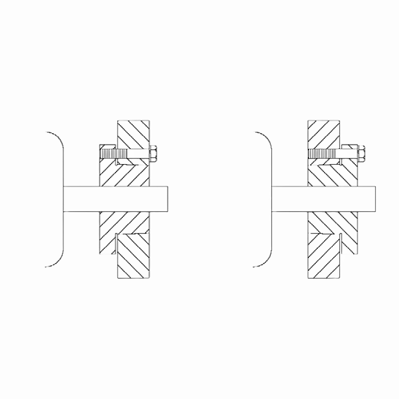
Conventional mounting involves inserting the bolts through the sprocket/sheave first, then threading them into the bushing. The assembly is then positioned onto the shaft with the bushing flange facing inward and the bolt heads facing outward, as illustrated in Figure 2.
Reverse mounting, on the other hand, requires placing the bolts through the bushing first, and then threading them into the sprocket/sheave. The assembly is then placed onto the shaft with the sprocket/sheave facing inward and the bolt heads facing outward, as depicted in Figure 2. Conventional mounting is typically the preferred method.
1) Thoroughly clean the shaft, bushing bore, outside of the bushing, and the sprocket/sheave hub bore to remove any oil, paint, or dirt. Additionally, ensure to file away any burrs.
Note: Avoid lubricating the bushing taper, hub taper, bushing bore, or shaft to prevent the risk of sprocket/sheave hub fracture. DO NOT USE LUBRICANTS.
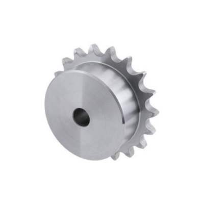
2) To assemble the sprocket/sheave and bushing, begin by sliding the sprocket/sheave onto the tapered bushing surface, ensuring proper alignment. Align the unthreaded holes in the sprocket/sheave hub with the threaded holes in the flange of the bushing. Proceed to hand-tighten the cap screws with lock washers installed. Then, mount the sprocket/sheave and bushing assembly onto the shaft, positioning the bushing flange either inward or outward based on your configuration requirements. Some assemblies allow for a reverse mount, with the bushing flange facing outward while still facilitating cap screw installation from the outside of the assembly.
3) With the key resting in the shaft keyway, position the assembly onto the shaft, allowing for slight axial movement of the sprocket/sheave, which may occur during the tightening process. Alternatively, for installing large or heavy parts in a conventional mount, it might be easier to mount the key and bushing on the shaft first. Then, place the sprocket/sheave on the bushing and align the holes accordingly.
Note: When mounting sprockets/sheaves on a vertical shaft, take precautions to prevent the sprocket/sheave and/or bushing from falling during installation.
4) Alternatively, tighten the cap screws in sequence until the sprocket/sheave and bushing tapers are fully seated together. Apply approximately half of the recommended bolt torque as specified in Table 2.
5) Inspect the alignment and axial runout (wobble) of the sprocket/sheave, and make adjustments as needed to ensure proper alignment.
6) Continue alternating the tightening of the cap screws until reaching the recommended torque values specified in Table 2 below. Do not exceed the recommended torque once reached.
Note: Excessive bolt torque can lead to sprocket/sheave and/or bushing breakage. When properly mounted, there should be a gap between the bushing flange and the sprocket/sheave.
7) When available, tighten the set screw to securely hold the key in place during operation.
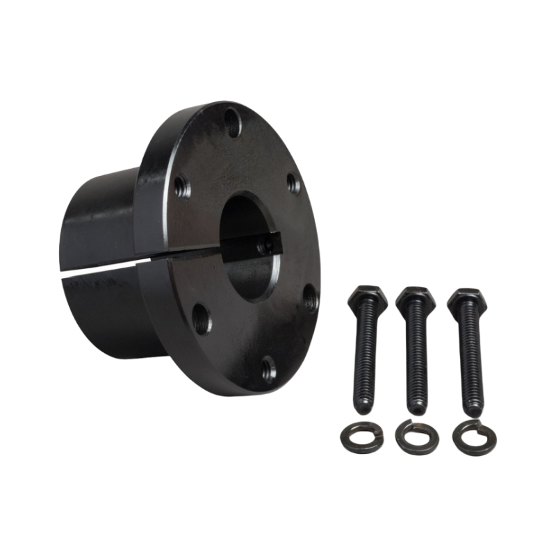
Table 2 – QD Bushing Bolt Torque Values
Caution: Excessive bolt torque can lead to sprocket/sheave and/or bushing breakage.
Note: To ensure proper drive performance, it is recommended to achieve full bushing contact on the shaft.
7) When available, tighten the set screw to securely hold the key in place during operation.
Remove QD Bushing
1) Loosen and remove all mounting bolts.
2) Insert cap screws into all threaded jack screw holes.
3) Loosen the bushing by first tightening the screw furthest from the bushing saw slot, then, alternately tighten the remaining screws. Keep tightening the screws in small but equal increments until the tapered sprocket/sheave and bushing disengage.
Note: Excessive or unequal pressure on the bolts can break the bushing flange, making removal impossible without destroying the sprocket/sheave.
QD Bushing Selection
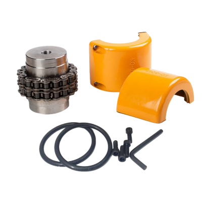
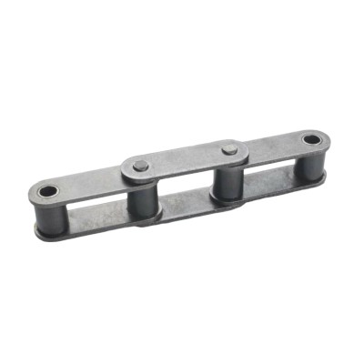
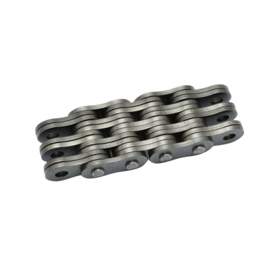
CTS®-ChinaTransmissionS is a professional power transmission parts supplier. We offer various taper bushings and hubs, and also manufacture industrial sprockets, roller chains, conveyor chains, v-belt pulleys, timing pulleys, gears & racks, etc.
If you need any help, please contact us.