How to measure Chain Sprockets?
Chain Sprockets Measurement
Accurate measurement of sprockets is essential for wholesale procurement, as it ensures compatibility, efficiency, and cost-effectiveness.
✔ Compatibility with Chains:
Precise measurements guarantee that the sprockets fit perfectly with the corresponding roller chains.
✔ Performance Optimization:
Properly sized sprockets enhance the efficiency and durability of machinery, reducing wear and tear on chains and sprockets.
✔ Standardization:
For bulk orders, consistent measurements ensure that all sprockets meet the required standards.
✔ Cost Savings:
Correctly measured sprockets prevent returns or replacements due to mismatched components.
✔ Custom Solutions:
Accurate measurements allow for customization in cases where standard sizes may not suffice, catering to unique operational requirements.
Chain Sprockets Measure
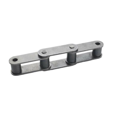
Roller Chain Type and Chain Pitch
Chain Sprockets are tailored for specific chain types, each adhering to a particular standard. Roller Chains are distinguished by their "pitch," denoting the distance between one roller-pin center to the next. ANSI chain pitch is consistently measured in 1/8” increments. There are, of course, metric standard roller chains other than ANSI.
For guidance on measuring ANSI and Metric chain pitch, consult Figure 1, followed by a reference to Table 1 for ANSI and Metric Standard Chain pitch sizes.
Table 1. ANSI and Metric Standard Chain Pitch Sizes
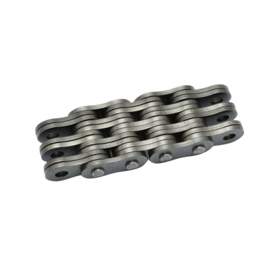
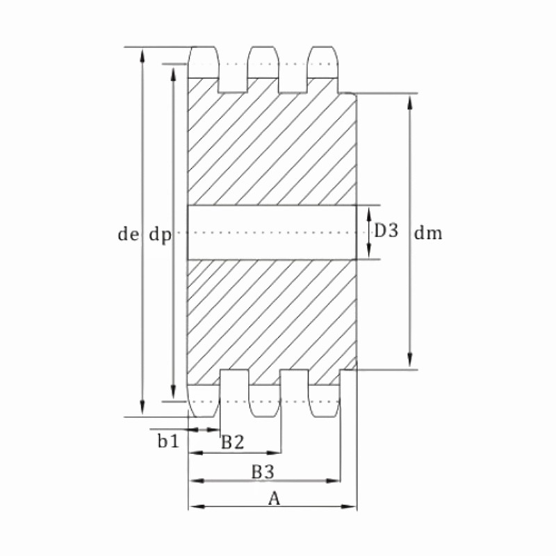
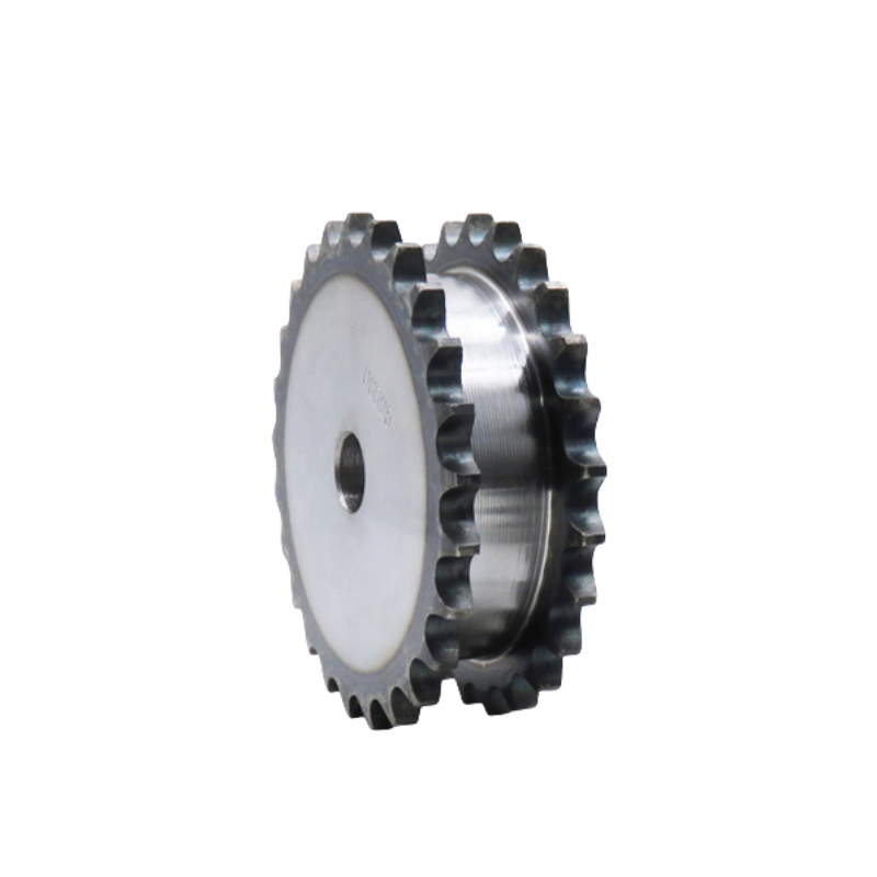
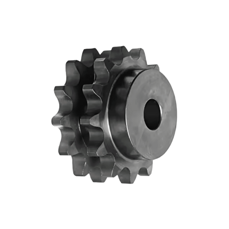
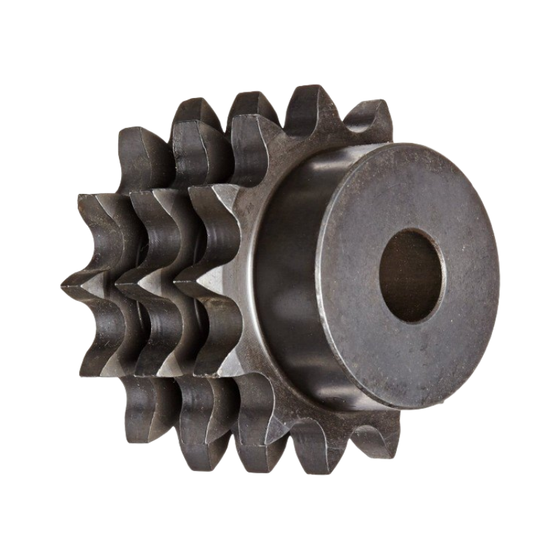
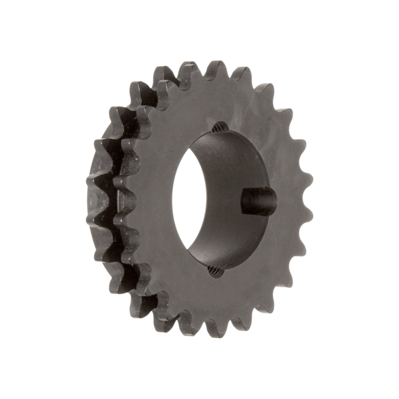
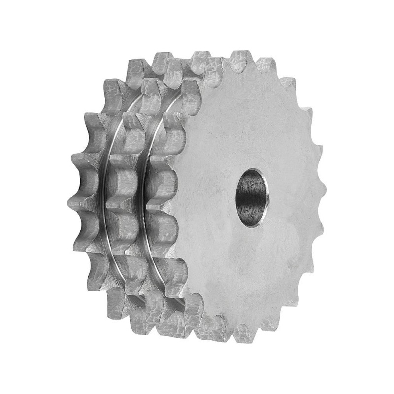
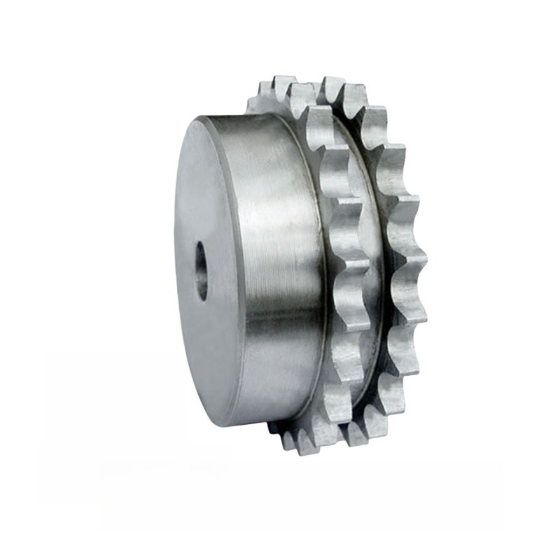
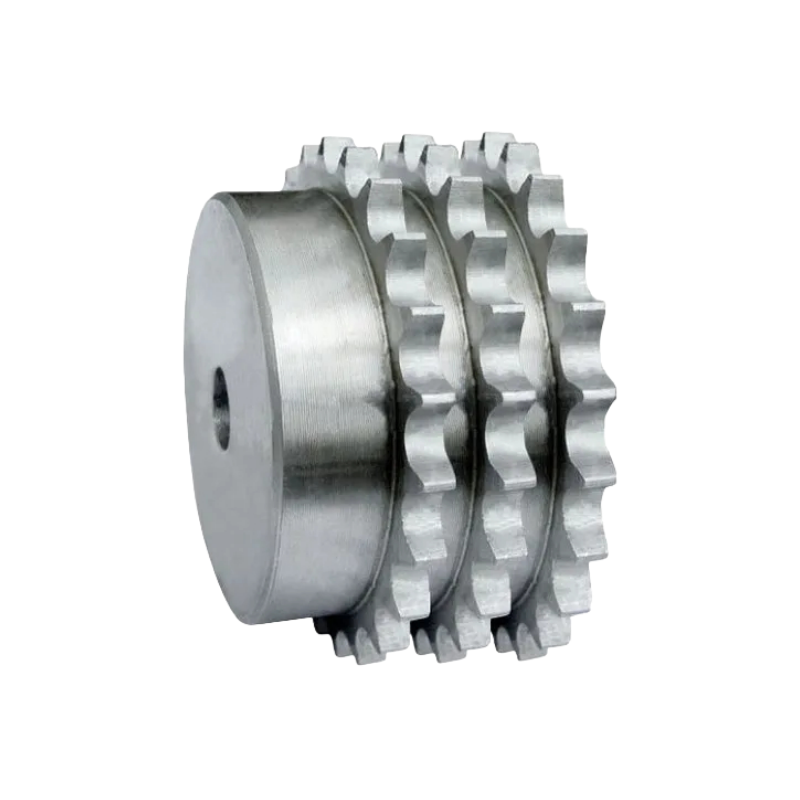
After establishing the chain pitch, it's crucial to take into account the number of chain strands utilized in the application: whether it's a single strand, double strand, triple strand, and so forth. The selected sprocket must match the chain configuration; for instance, a double-strand chain necessitates a double-strand sprocket. (See Fig. 2 for reference.)
Table 2. Single-strand and Triple-strand chain sprocket profile
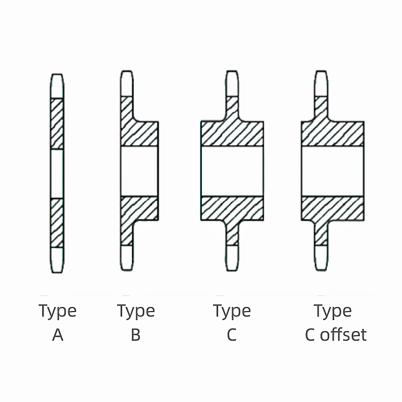
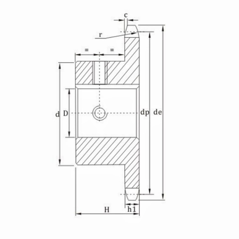
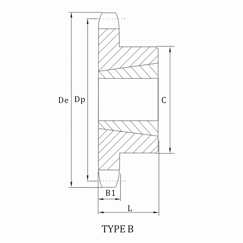
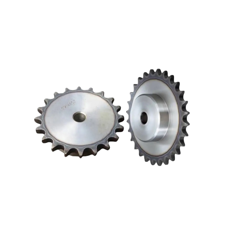
Sprocket Hub Style
Although roller chain sprockets come in numerous configurations, they predominantly adhere to three major hub styles:
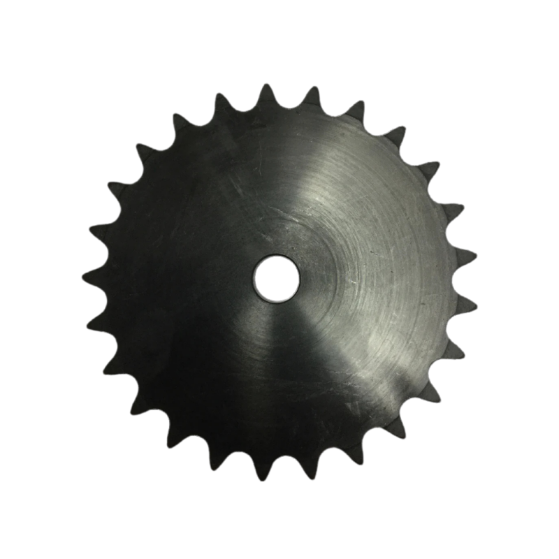
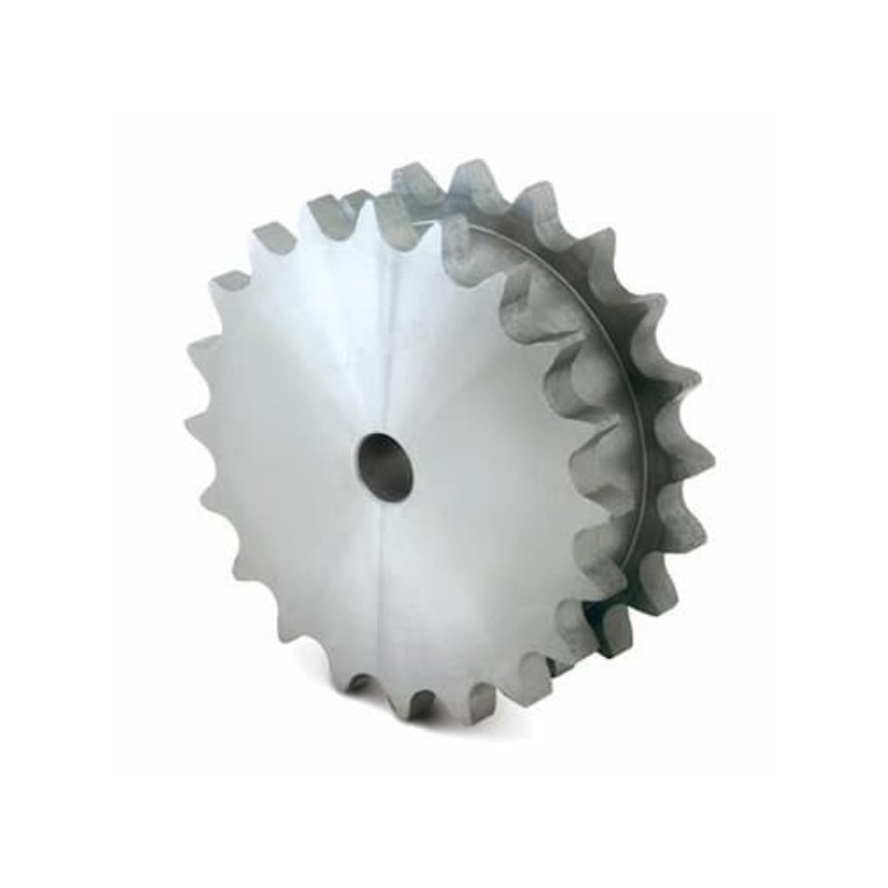
A-Hub: No extension on either side of sprockets (Type A)
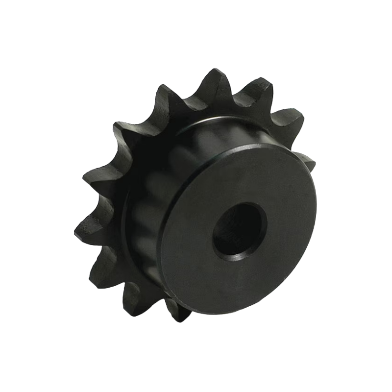
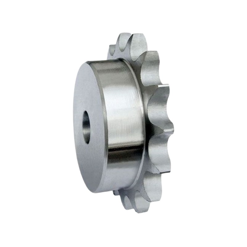
B-Hub: Extension on one side of sprockets (Type B)
C-Hub: Extension on both sides of sprockets (Type C)
For visual reference, please consult Figure 3.
Table 3. Single-strand and Triple-strand chain sprocket profile
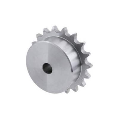
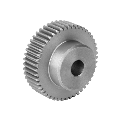
Number of Sprocket Teeth or Sprocket Diameter
Determining the number of sprocket teeth is typically straightforward: just count them. However, if the teeth are worn or damaged, it might be challenging. In such cases, you can use a caliper to measure the diameter of the sprocket, which can aid in identification.
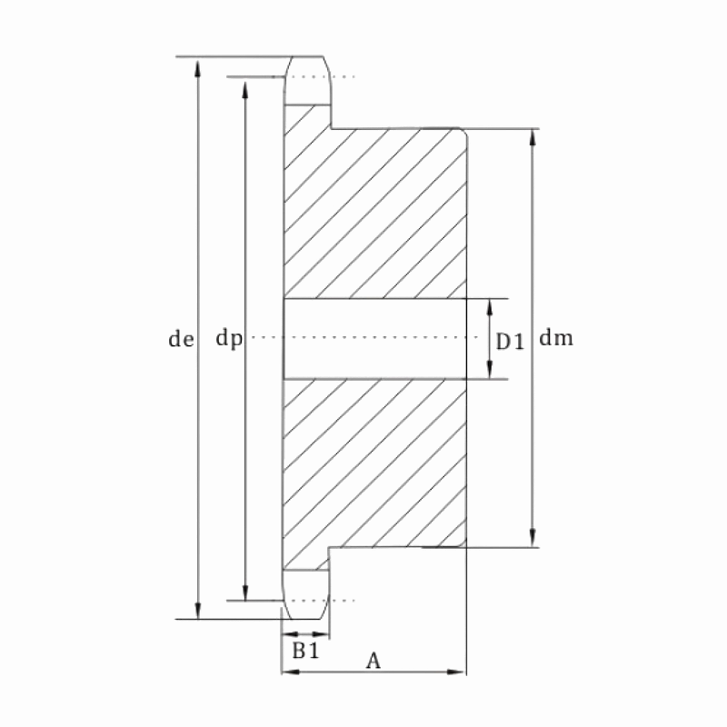
Fig. 4. Primary sprocket dimensions
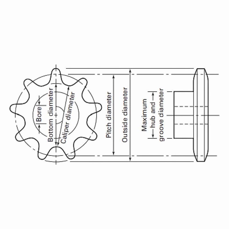
Hub Diameter on B and C Hub Sprockets
The outer diameter of the hub is referred to as the "hub diameter," usually provided by the sprocket supplier. This diameter is determined by factors such as the size of the sprocket bore, the keyway utilized, and the necessity to uphold a sprocket-wall thickness capable of withstanding the application's required forces. (Please refer to Fig. 4 for further illustration.)
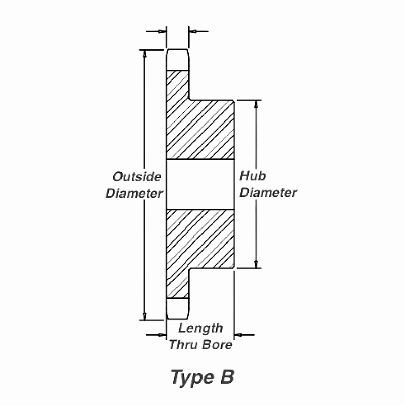
LTB (Length Through Bore)
"LTB" refers for Length Through Bore, signifying the inside hub diameter and the extent to which it is machined. This length must be sufficient to accommodate the appropriate-size keyway, ensuring it can withstand the shear and torque stress generated by the rotating shaft. (Refer to Fig. 5 for visual representation.)
Fig. 5. Primary sprocket dimensions
Sprocket Bore Types
The sprocket bore refers to the inside diameter of the sprocket and its method of attachment to the shaft.
"Plain bore/Pilot bore" is associated with A-hub, B-hub, and C-hub sprockets, where no special machining is performed for keyways or set screws. These sprockets only feature a hole to accommodate the shaft diameter, often requiring additional machining before installation.
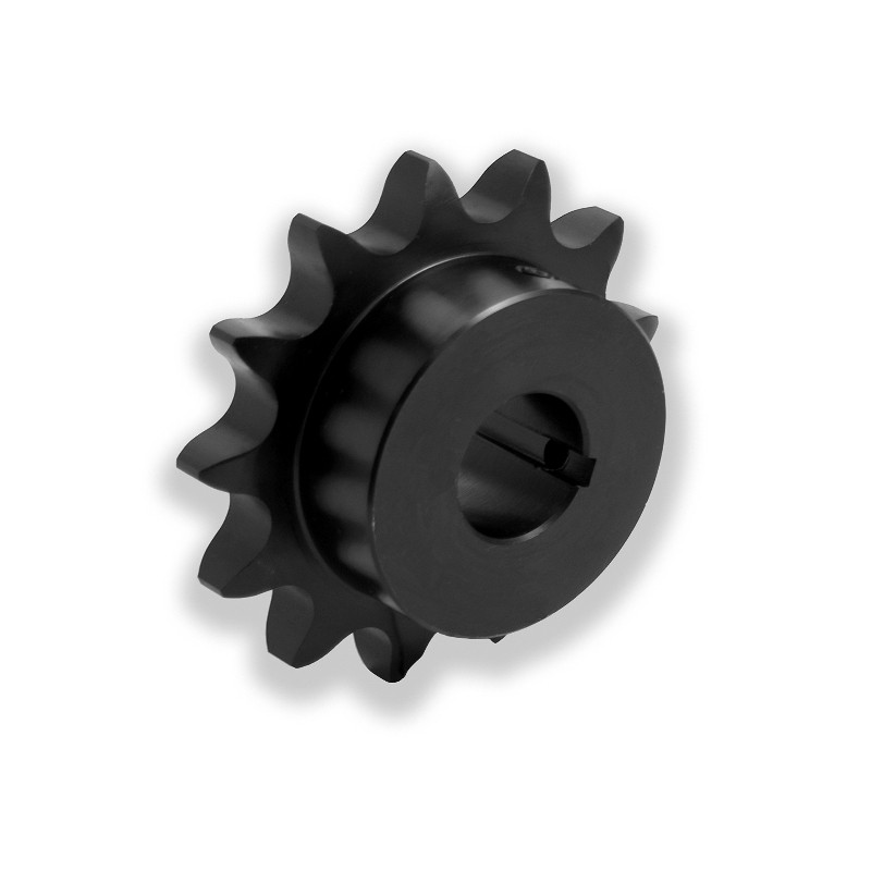
"Finished bore" is linked with B- and C-style sprockets, where the hub's inside diameter is machined to fit a specific shaft diameter. This configuration includes a standard keyway and set screws, with CTS® providing two set screws for added clamping force. Finished bore hubs can also be machined to meet non-standard yet specific requirements based on the application needs. (Refer to Fig. 6 for a standard finished bore sprocket.)
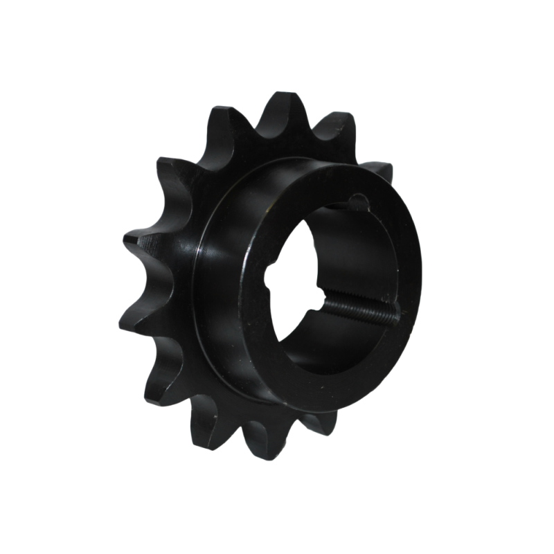
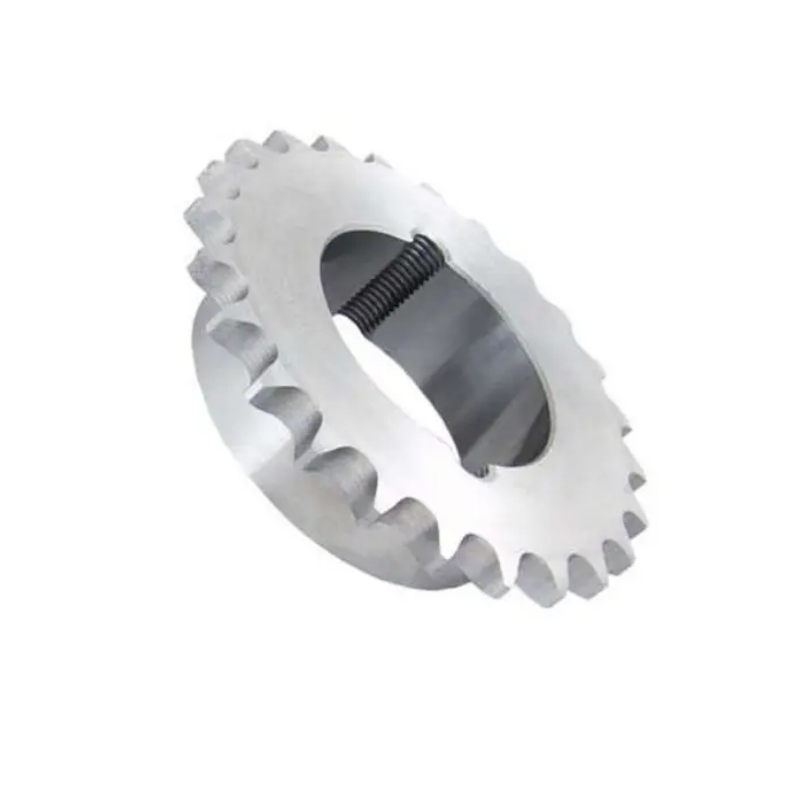
"Taper bore" refers to a specialized type of sprocket bore design that features a tapered inner diameter. This design allows for a tight and secure fit onto a shaft with a matching taper, ensuring optimal transmission of power and torque. Taper bore sprockets are commonly used in applications where precise alignment and maximum torque transmission are critical, such as in heavy machinery, conveyor systems, and automotive components. The taper bore design facilitates easy installation and removal while providing a reliable and durable connection between the sprocket and shaft.
"Maximum bore diameter" is another term associated with B- and C-style sprockets, denoting the maximum bore size to which a sprocket can be machined without compromising structural integrity while still accommodating a standard keyway. This measurement is typically listed in the vendor's catalog.
Fig. 6. Sprockets Bore
Plain Bore/Pilot Bore Sprockets
Finished Bore Sprockets
Taper Bore Sprockets
Keyway Dimensions and Set-screw Locations
Sprockets are typically affixed to the shaft using ANSI standard dimensioned keyways and one or more set screws. ANSI standards dictate keyway specifications in terms of length, width, and depth for a given shaft diameter. Refer to Fig. 7 for a partial listing of common keyway dimensions. However, if your application deviates from this standard, you'll need to measure or reference the proper-size keyway and provide this information to your sprocket supplier.
A set screw serves to prevent axial movement of the sprocket, usually positioned above the keyway. This placement prevents both the sprocket and key from shifting along the shaft. To enhance sprocket retention, CTS® includes two set screws as standard practice. The second set screw, positioned at 90° to the keyway, offers additional clamping force and reduces side forces on the key, thereby extending service life.
Fig. 7. Keyway dimension and set-screw
☆Hub size may require smaller setscrews in some instances.
Hardened-Tooth Sprockets
When the chain engages with the sprocket, frictional wear between the tooth and chain occurs. Every rotation brings each sprocket tooth into contact with the chain. Sprockets are commonly manufactured by stamping from plate, pressing from powder metal, or machining from bar stock. The hardness of the tooth significantly impacts sprocket longevity. Sprockets with hardened teeth have the potential to last three times longer than softer sprockets. While this option enhances durability, may charge an additional fee for it.
Fig. 8. Chain Sprockets with Hardened Teeth
Other Common Sprocket
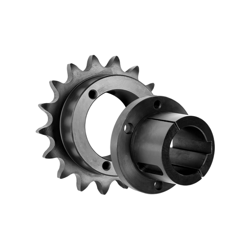
Bushed Sprockets
Bushed sprockets are employed in applications with higher working loads. Those with tapered bushings belong to families like QD, Split-Taper, or Taper-Lock. QD and Split-Taper bushings feature flanges, secured to the sprocket with large anchor bolts around the flange's circumference (refer to Fig. 9). Taper-Lock bushings, similar in function, incorporate a split through the taper, ensuring a secure clamp on the shaft with a series of set screws on the bushing's outer diameter (parallel to the shaft) (see Fig. 9).Fig. 9. Sprockets with QD Bushings
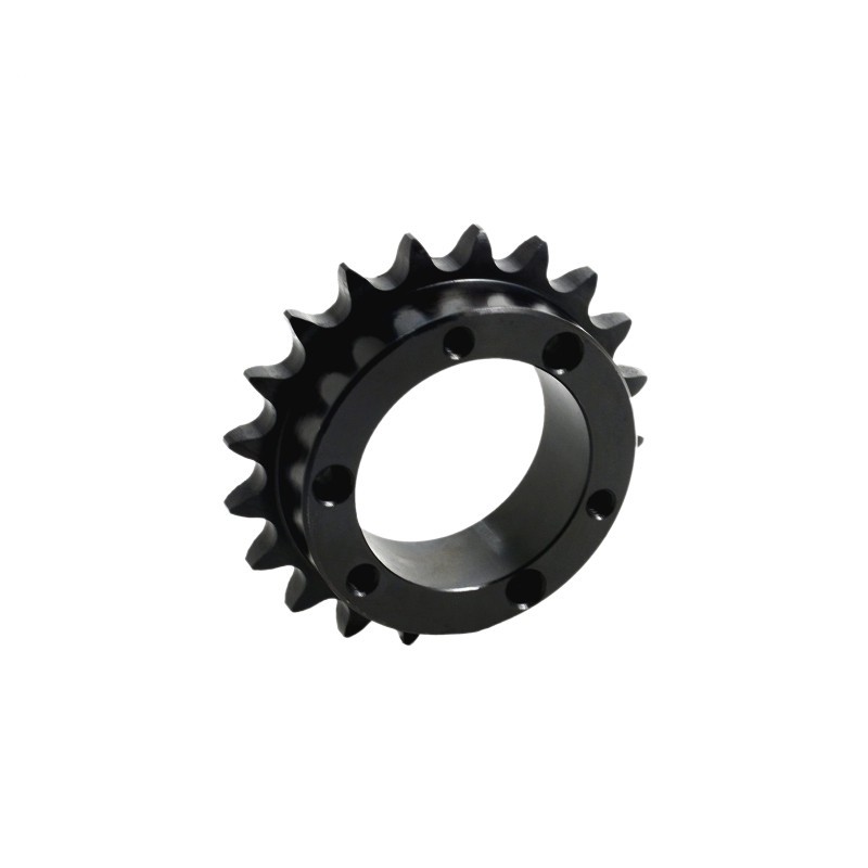
Sprockets with QD Bushings
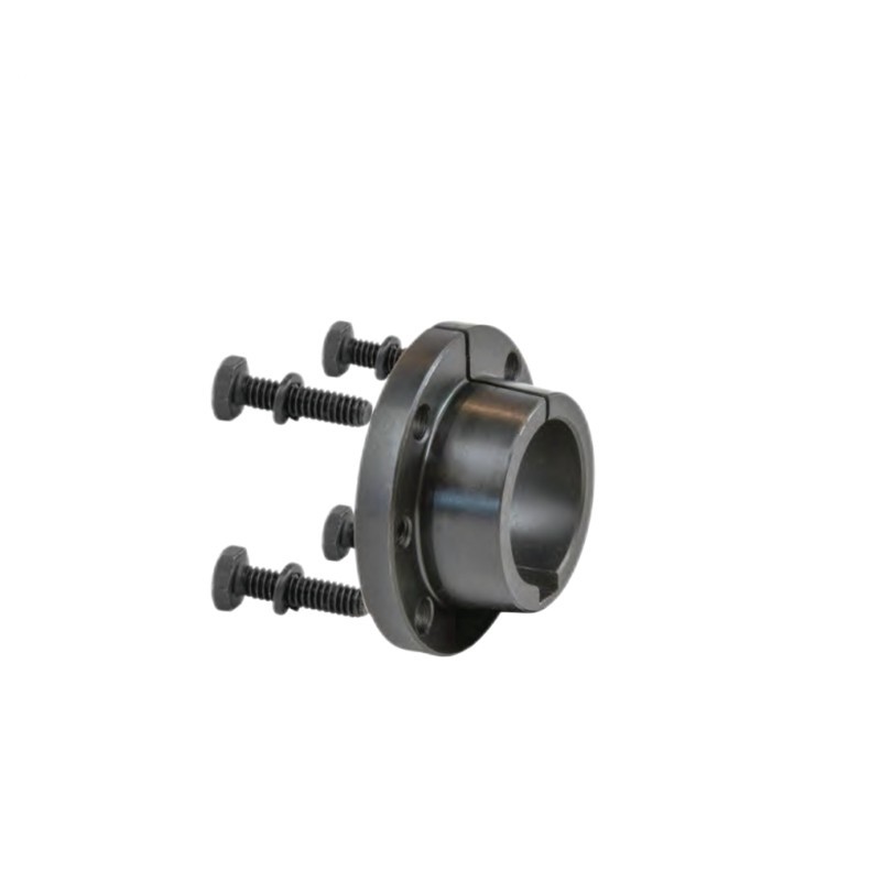
QD Bushings
Steel Split Sprockets
These sprockets (depicted in Fig. 10) are cut entirely through the diameter for easy installation and removal. Held together by bolts on either side of the hub, this style is typically available in chain pitch sizes ranging from 40 to 240 and bore diameters from 3/4” to 6”, depending on the selected chain pitch.Fig. 10. Sprockets with Split Bushings
Double Single Sprockets
Utilized in scenarios where multiple items are powered by a common drive shaft, these sprockets (as shown in Fig. 11) feature wider spacing between the sprocket plates, allowing two independent chain strands to engage without contacting each other. With this design, each chain strand may exit in different directions—one towards the ceiling and the other parallel to the floor.Fig. 11. Double Sprockets for Two Single Chains
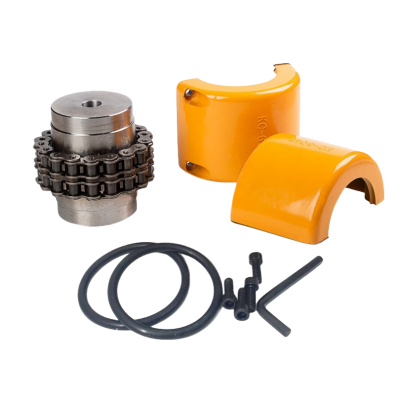
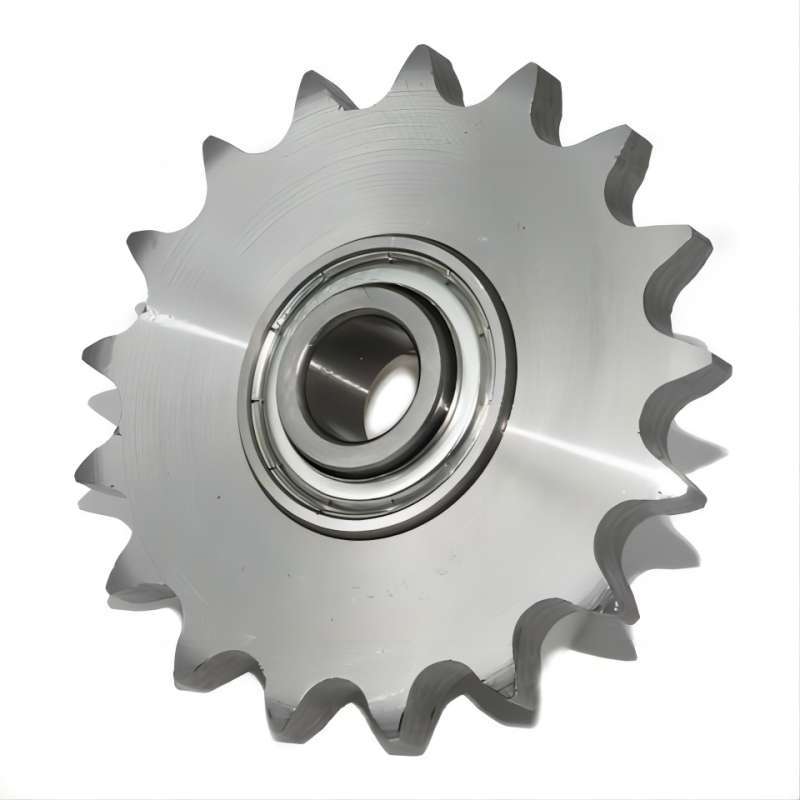
Idler Sprockets and Chain Tensioners
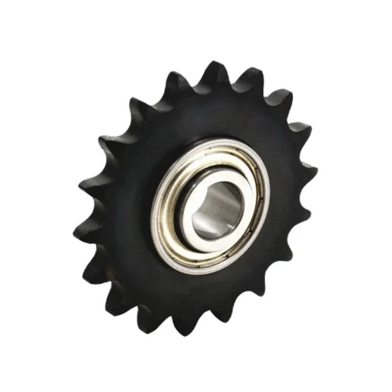
These components are deployed in applications where the drive chain might experience slack due to lengthy spans, non-adjustable driven shafts, or obstructions. They prevent chain whipping and ensure even load distribution. Additionally, they can be used in applications where the drive chain's direction may be reversed, with the idler sprocket mounted outside the chain to prevent whipping. Fig. 12 illustrates a ball-bearing idler sprocket and bronze bushing for reference.
Fig. 12. Idler Sprockets with Ball Bearing
ANSI Chain Sprocket
Metric Chain Sprocket

CTS® | Professional Industrial Sprocket Manufacturer
CTS® is a professional industrial sprocket manufacturer with over 14 years of experience in the power transmission industry. We have our industrial sprocket factory and a professional technical team that can provide technical support and a responsive after-sales team after-sales team.
As a professional industrial sprocket manufacturer with mature industrial sprocket manufacturing technical, we can not only produce standard industrial sprockets(ANSI/DIN/KANA) but also customize industrial sprockets according to your specific needs.
If you have any questions about industrial sprockets and other transmission parts, please contact us to help you.
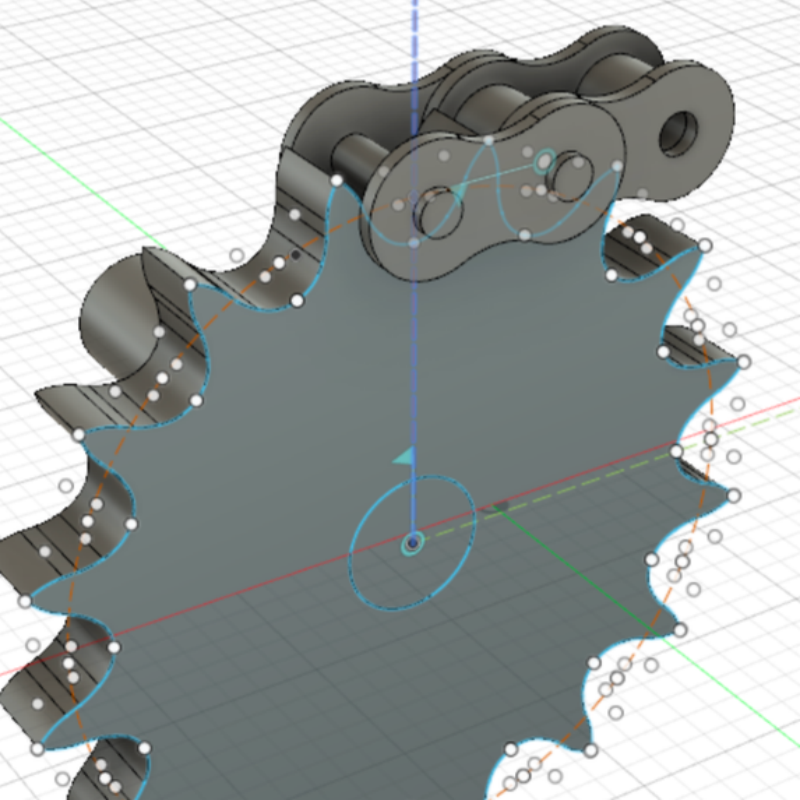
Industrial Sprocket CAD
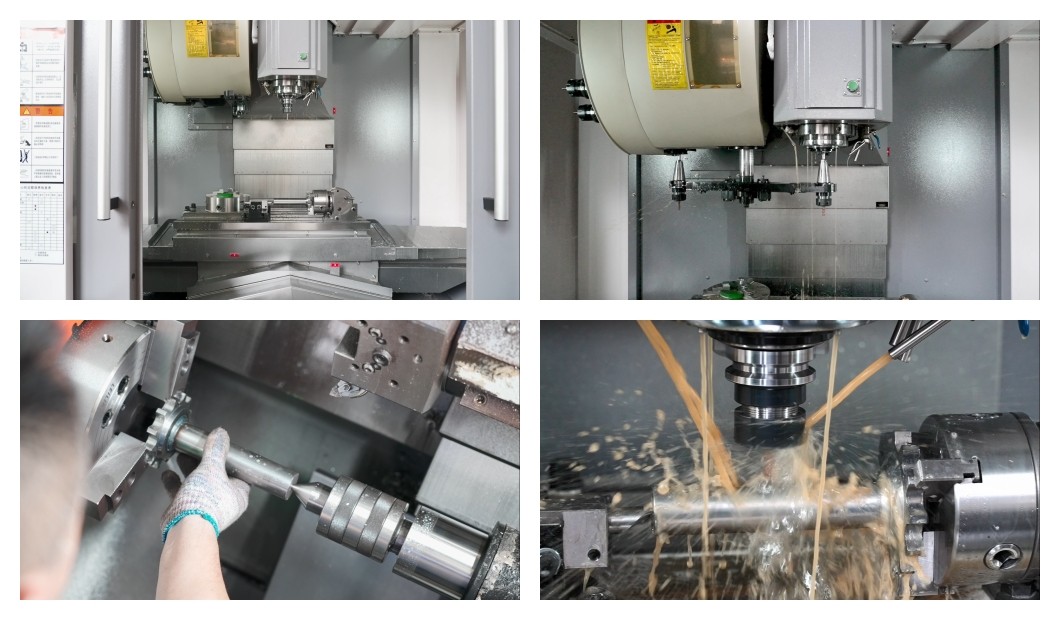
CNC Machining
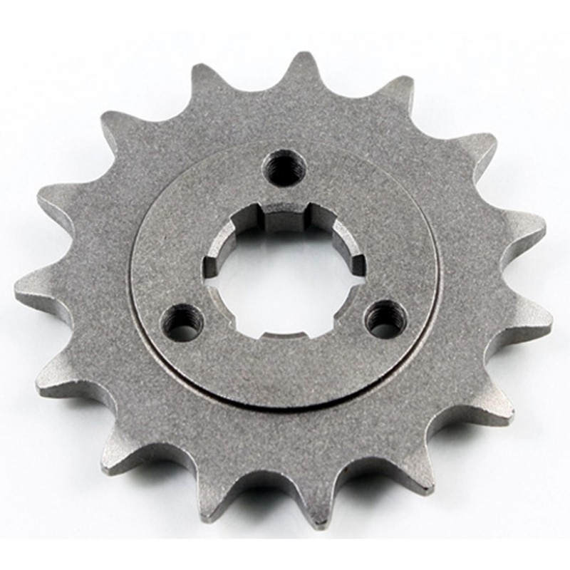
Customized Sprockets